|
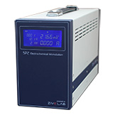
Power amplifier (CE) |
|
|
Power
|
24Watt(12V@2A)
|
|
Compliance voltage
|
±12V |
|
Max. current |
±2A |
|
Control speed selection |
8ea |
|
Bandwidth |
4MHz |
|
Slew rate |
15V/usec |
|
Potentiostat mode(voltage control) |
|
|
Voltage control |
|
|
Control voltage range |
±10, ±1V, ±100mV |
|
Voltage resolution |
16 bit per each range |
|
Voltageaccuracy |
±0.02% fs(gain x1)
|
|
Max. scan range |
±10V vs. ref. E |
|
Current measurements |
|
|
Current range |
11 ranges (auto/manual setting)
2nA to 2A (200pA with gain) |
|
Current resolution |
16 bit;
60uA, 6uA, 600nA, 60nA, 6nA, 600pA
60pA, 6pA, 600fA, 60fA, 6fA |
|
Current accuracy |
±0.02%f.s.(gainx1)>200nA
|
| Galvanostat mode(current control) |
|
| Current control |
|
|
Control current range
|
max. ±2A
± full sacle depending on selected range
|
|
Current resolution
|
16 bit;
60uA, 6uA, 600nA, 60nA, 6nA, 600pA
60pA, 6pA, 600fA, 60fA, 6fA
|
|
Current accuracy
|
±0.02% f.s.(gain x1) >200nA f.s.
|
| Voltage measurements |
|
|
Voltage range
|
10V, 1V, 100mV |
|
Voltage resolution
|
16 bit; 0.3mV, 30uV, 3uV
|
|
Voltage accuracy
|
±0.02% fs (gain x1)
|
| Electrometer |
|
|
Max. input voltage
|
±10V |
|
Input impedance
|
2x10¹³Ω||4.5pF
|
|
Bandwidth
|
>22MHz
|
|
CMRR
|
>114dB
|
| EIS(Internal FRA) for system |
|
|
Frequency range
|
10uHz ~ 2MHz
|
|
Frequency accuracy
|
<0.01%>
|
|
Frequency resolution
|
5000/decade
|
|
Amplitude
|
0.1mV ~ 5V rms (potentiostatic)
0.1 ~ 70% f.s. (galvanostatic)
|
|
Mode
|
Static EIS:
potentiostatic, galvanostatic,
pseudo-galvanostatic, OCP
Dynamic EIS:
potentiodynamic, galvanodynamic
Fixed frequency impedance:
potentiostatic, galvanostatic,
potentiodynamic, galvanodynamic
Multisine EIS:
potentiostatic, galvanostatic
|
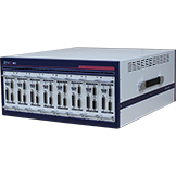
| Main system |
|
|
PCcommunication
|
USB2.0 high speed
|
|
Line voltage
|
100~240VAC, 50/60Hz, 1Amp
|
|
Max. channel number per unit
|
8 independent channel per unit
|
|
Max. channel
|
32 channels(4 units) expandable per PC
|
|
Size/Weight
|
448.7x188.4x535.4mm(WxHxD) / 23.3kg(8ch)
|
| Software |
|
|
Max. steps per experiments
|
1000
|
|
Shutdown safety limits |
voltage, current, temperatrue etc. |
|
Max. sampling rate |
2usec or 3usec depending on data point numbers |
|
Min. sampling time |
unlimited |
|
Sampling condition |
time, dv/dt, dI/dt, temperature etc.
|
|
Interface for system |
|
|
Auxiliary port |
|
|
- Digital output
|
3 (open collector)
|
|
- Digital input
|
2 (photo coupler)
|
|
- Auxiliary voltage inputs
|
3 analog input: ±10V
for measurement of WE vs. CE
CE vs. RE or other signal
|
|
- Analog output
|
1 analog output : ±10V
for stirrer, MFC, RDE etc.
|
|
Misc.port
|
|
| -Signalgeneratoroutput
|
1 analog output for FRA output or
waveform generation output
|
|
-Peripheralcommunication
|
12C to control external devices
|
|
- Temperature measurement
|
1 K-type thermocouple input
|
|
- Zero resistance ammeter
|
2nA ~ 2A ranges
|
|
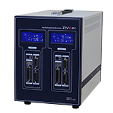
Channel System
|
|
|
Cell cable
|
1 meter shielded type (standard)
working, reference, counter, working sense
|
|
Control
|
DSP with FPGA
|
|
DAC
|
2x16bit DAC(50MHz) for bias & scan
1x16bit DAC(1MHz) for analog output
|
|
Dataacquisition
ADC
|
2x16bit ADCs(500kHz) for voltage & current
1x16bit ADCs(250kHz) for auxiliary voltage &
temperature reading
|
|
Calibration
|
Automatic
|
|
Filter selection
|
4ea(5Hz, 1kHz, 500kHz, 5MHz)
|
|
Scan rate
|
0 ~ 200V/sec in common mode
0 ~ 5000V/sec in fast mode
|
|
LED indicator
|
busy, run
|
|
Internal data memory
|
542,000 points
|
|
Max. output power
|
30Wattper channel
|
|
PC requirement
|
|
|
Operating system
|
WindowsXP SP3/7/8/10(32bit/64bit OS)
|
|
PC specification(minimum)
|
Pentium4, RAM 1GB or higher
|
|
Display
|
1600x900 high color or higher
|
|
USB
|
high speed 2.0
|
|
General
|
|
|
Dummy cell
|
One external dummy cell included
|
|
Thermocouple
|
1.5meter K-type (option)
|
| Auxiliary cable
|
Option
|
| Misc. cable
|
Option
|
|
Impedance analysis software
|
ZmanTM
|
|
DC data analysis software
|
IVmanTM
|